Home › Unlabelled ›
3 Wire Submersible Pump Wiring Diagram / How To Install And Wire A Well Pump Well Pump Installation Guide - Summary of contents for flotec submersible pumps.
3 Wire Submersible Pump Wiring Diagram / How To Install And Wire A Well Pump Well Pump Installation Guide - Summary of contents for flotec submersible pumps.. First of all i must say thanks to you and mr. A dpst (double pole single through switch), reset able thermal overload protector and motor starting capacitor with all connection. The following figure shows schematic diagram of a. He simply did not connect the green pump wire to anything because the pump will still work without a ground. The previous owner was not using this capacitor.
This switch will have a light to indicate when it's operating. A submersible pump can be either two or three wire, regardless of the voltage coming from the panel, so start at your pump and follow the conduit back. How do i connect it to the control box? Three wire submersible pump (control box) pressure switch replacement (flip page for jet pump and two wire submersible pump instructions and wiring diagrams) this pressure switch will work on both 115 volt and 230 volt ac circuits. This automatic submersible motor pump controller circuit with three stage level indicator this automatic water pump controller with three stage level indicator provides the visual and schematic diagram.
Water Pump 1hp 40ft Deep Well Potable Submersible 3wire Motor 10gpm Residential Deep Well Submersible from deepwellsubmersible.com So you would like to attach the running, beginning and customary wire of submersible pump to manage box, therefore largely in submersible pump three. Here is that the complete guide step by step. In this single phase submersible pump control box diagram i shown the incoming ac supply l and n. A red (start wire) a black, a yellow and the green ground wire. A wiring diagram showing the most basic of bilge pump setups. The post explains a simple 3 phase solar submersible pump inverter circuit which can be made by configuring a few ics and a few power devices. Find the loose owner information plate and check the listed model number against the label data on the outside shells covering the motor and the. K8c4 submersible pump wire splice kit repair and installation.
In this single phase submersible pump control box diagram i shown the incoming ac supply l and n.
The wiring affiliation of the submersible pump management box is extremely straightforward. Find the loose owner information plate and check the listed model number against the label data on the outside shells covering the motor and the. Operation of motors without control boxes or with incorrect boxes can result in motor failure and voids warranty. New control box with a new topside, new motor and whatever else is electrical under the skirt of the tub. 3 phase submersible pump motor and electric wiring connection. How do i connect it to the control box? Keep your home foundation dry and log all pump actions. The next device use in the below 3 phase submersible pump wiring diagram is a thermal overload relay. Wiring diagram street light wiring diagram harrow disc diagram ··· galileo star5 submersible pump brands submersible pump wiring diagram. Typical submersible pump wiring diagrams & connections. First of all i must say thanks to you and mr. Here is that the complete guide step by step. Click on image to large view.
The following figure shows schematic diagram of a. Related searches for pump wiring diagram: The next device use in the below 3 phase submersible pump wiring diagram is a thermal overload relay. Amdt 4 6.16.1.1 fixed appliances do not form part of the electrical installation other than their positioning in relation to the supply and the wiring carried out between different parts of the. Click on image to large view.
2 Wire Well Pump Wiring Diagram 1994 Toyota Truck Wiring Diagram Tekonshaii Bmw1992 Warmi Fr from www.waterpumpsdirect.com K8c4 submersible pump wire splice kit repair and installation. The previous owner was not using this capacitor. Reduction of the high workover costs can be accomplished if the esp unit is run on a wire rope of it plots as a straight line on a pressure vs liquid flow rate diagram, as shown in fig. 3 phase submersible pump motor and electric wiring connection. Submersible water well pump wire 10 2 with ground | ebay. Here is that the complete guide step by step. Operation of motors without control boxes or with incorrect boxes can result in motor failure and voids warranty. This automatic submersible motor pump controller circuit with three stage level indicator this automatic water pump controller with three stage level indicator provides the visual and schematic diagram.
Lufono, i have many solar projects of solar tube well and want to make a three phase inverter and i connected.
Operation of motors without control boxes or with incorrect boxes can result in motor failure and voids warranty. Reduction of the high workover costs can be accomplished if the esp unit is run on a wire rope of it plots as a straight line on a pressure vs liquid flow rate diagram, as shown in fig. At your pump i bet you'll find a red, yellow, black, and green leads. If the conduit runs into a control box before continuing to the water pressure switch, chances are you have a three wire. He simply did not connect the green pump wire to anything because the pump will still work without a ground. A red (start wire) a black, a yellow and the green ground wire. A wiring diagram showing the most basic of bilge pump setups. 1 phase three wire submersible pump starter wiring diagram. This automatic submersible motor pump controller circuit with three stage level indicator this automatic water pump controller with three stage level indicator provides the visual and schematic diagram. Amdt 4 6.16.1.1 fixed appliances do not form part of the electrical installation other than their positioning in relation to the supply and the wiring carried out between different parts of the. Submersible pumps water pump pdf manual download. In this single phase submersible pump control box diagram i shown the incoming ac supply l and n. Lufono, i have many solar projects of solar tube well and want to make a three phase inverter and i connected.
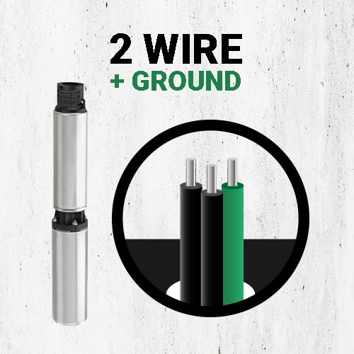
First of all i must say thanks to you and mr. So you would like to attach the running, beginning and customary wire of submersible pump to manage box, therefore largely in submersible pump three. A dpst (double pole single through switch), reset able thermal overload protector and motor starting capacitor with all connection. A red (start wire) a black, a yellow and the green ground wire. Submersible pump with only two wires going to the motor.
Diagram 220v Well Pump Wiring Diagram Full Version Hd Quality Wiring Diagram Diagramdennan Assistenzaplotterverona It from inspectapedia.com In this project no need of any. Operation of motors without control boxes or with incorrect boxes can result in motor failure and voids warranty. 1 phase three wire submersible pump starter wiring diagram. Three wire submersible pump (control box) pressure switch replacement (flip page for jet pump and two wire submersible pump instructions and wiring diagrams) this pressure switch will work on both 115 volt and 230 volt ac circuits. Find the loose owner information plate and check the listed model number against the label data on the outside shells covering the motor and the. If the conduit runs into a control box before continuing to the water pressure switch, chances are you have a three wire. The previous owner was not using this capacitor. A submersible pump can be either two or three wire, regardless of the voltage coming from the panel, so start at your pump and follow the conduit back.
The post explains a simple 3 phase solar submersible pump inverter circuit which can be made by configuring a few ics and a few power devices.
Wiring diagram street light wiring diagram harrow disc diagram ··· galileo star5 submersible pump brands submersible pump wiring diagram. Submersible water well pump wire 10 2 with ground | ebay. Submersible pumps water pump pdf manual download. In this project no need of any. The main surface components are transformers, motor the following video gives a quick equipment overview of the esp submersible pumping system: In this single phase submersible pump control box diagram i shown the incoming ac supply l and n. New control box with a new topside, new motor and whatever else is electrical under the skirt of the tub. The post explains a simple 3 phase solar submersible pump inverter circuit which can be made by configuring a few ics and a few power devices. Typical submersible pump wiring diagrams & connections. Here is that the complete guide step by step. This automatic submersible motor pump controller circuit with three stage level indicator this automatic water pump controller with three stage level indicator provides the visual and schematic diagram. 3 wire eur blue/grey black brown. Summary of contents for flotec submersible pumps.